An Unusual Enginectomy
Part II
Vehicular Husbandry: The mounting of a sexy little European motor
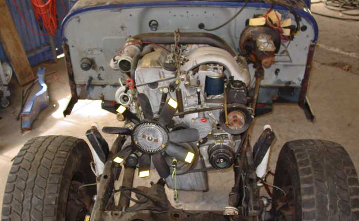
I wouldn't consider this a big deal if I had a MBZ G-Wagon with the same motor that I could do R&D (rip-off and duplicate) on. But alas, Mercedes never imported the diesel G-wagon so I had to figure out the motor mounting from scratch.
My first move was to hunt down the correct motor mounts. I did my research and found the premier US G-Wagon garage in New Mexico. The company is named Europa Imports and their parts guy Travis Boggus has been an incredible help. From my first phone call on, he has been enthusiastic, honest, and incredibly informative. Through Travis, I gained a MUCH higher respect for Mercedes. I learned that the Mercedes parts system covers ALL Mercedes parts for the entire world, not just vehicles brought into the USA. And when it came to having the motor mounts shipped in from Germany his reply was...You'll have them by the end of next week. Damn, it's taken me longer to get stuff from LA before.
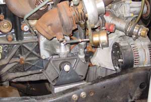
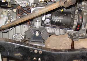
Once I had the motor mounts in hand, I had to figure out how to achieve the correct position of the motor in the X Y Z planes, pitch and yaw, while avoiding interference with the steering box, brake booster, and axle in full travel. Again this could have been much easier if there wasn't a bunch of stuffy Germany brainiacks involved. The mounts splayed out at some slight angle, The right mount was about 2 inches higher than the left and of course they weren't perpendicular to the line of the motor. All for some very good reason for sure.
Here is the blow by blow method that I used to the correct mounting.
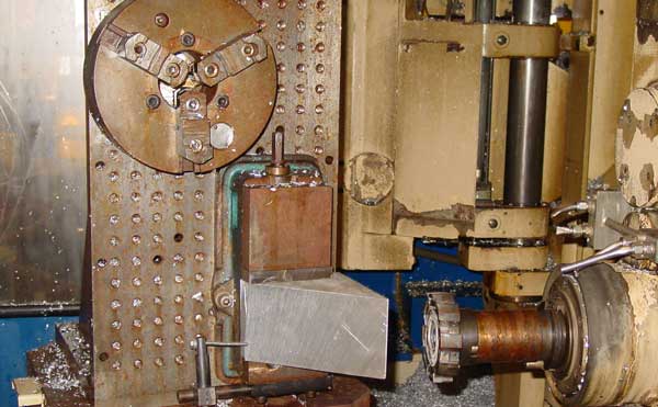
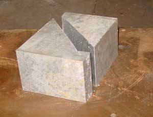
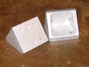
First I used my test bed to block up the motor into what I "believed" to be the correct position. I then used an angle protractor to find the angle of both motor mount brackets. Next I measured up the Jeep frame and holes for mounting the carrier brackets for the stock motor mounts. If this information in hand, I went to my CAD system and drew up an electronic model of the ONLY solid information I had, and that was not very much, but enough for me to start roughing out the new carrier brackets. Over designing at this stage would have been a bad mistake.
 <
<